
 DE
 IT
ZAHNRIEMENACHSEN
MIT UND OHNE MOTOR
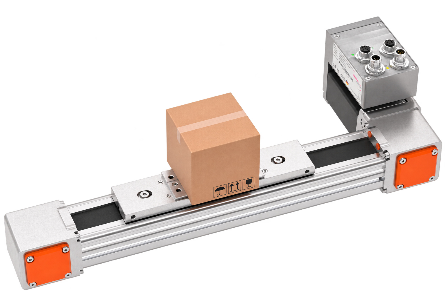
Timing belt axes for transport, positioning and handling.
The right linear axis for long travel distances—as a mechanical axis or paired with a stepper or servo motor.
With six product series, GUNDA supports a variety of motion tasks: from compact timing belt axes to flat profiles and vertical axes. Compare guide configurations, stroke, forces, and torques to find the right foundation for your machine.
We tailor the axis and motor to your application. For your existing motor, we’ll verify the appropriate flange and coupling connections.

The right guide. The right drive.
Travel distance and dynamics.
Series with strokes up to 6,700 mm. Speed, acceleration and moving mass are considered together.
Forces and moments.
Integrated, additional or double external guides: the load on the carriage determines the appropriate version.
Single axis or system.
Coordinate the mechanics and motor connection, including combinations of several axes for your handling task.
Compare timing belt axes. Six series at a glance.
Compare the key mechanical data. The values cover several sizes and guide variants.
On smaller screens, scroll the table horizontally.
| SIX SERIESYour timing belt axis. A direct comparison. |
|
 |
 |
 |
 |
 |
|---|---|---|---|---|---|---|
| 01 / Mechanics and travel | ||||||
| Sizes / versions | BK-1 / BK-2 | 42 / 55 / 80 / 105 | 55 / 80 | 55 / 80 | 42 / 42D · H / L | 55L / 55S / 80L / 80S |
| Stroke range / maximum stroke | up to 3,800 mm | 100–6,700 mm | 100–6,700 mm | 100–6,700 mm | up to 6,000 mm | 100–1,500 mm |
| Repeatability | ±0.05 mm | ±0.05 mm | ±0.05 mm | ±0.05 mm | ±0.05 mm | ±0.10 mm |
| Travel per revolution | 110 / 140 mm | 90 / 120 / 160 / 210 mm | 120 / 160 mm | 120 / 160 mm | 130 mm | 130 / 192 mm |
| Maximum input speed by version | up to 3,500 min⁻¹² | 850–2,000 min⁻¹ | 1,000 / 1,500 min⁻¹ | 1,000 / 1,500 min⁻¹ | 1,400 min⁻¹ | 500–900 min⁻¹ |
| 02 / Forces and moments | ||||||
| Maximum axial force Fx | 800–1,250 N | 460–2,750 N | 820–1,950 N | 820–1,950 N | 615 N | 1,250–2,500 N |
| Maximum transverse force Fy / Fz | up to 9,600 N¹ | up to 7,500 N | up to 17,170 N | up to 20,200 N | 1,275 N | up to 7,800 N |
| Maximum moment Mx | up to 150 Nm¹ | up to 120 Nm | up to 527 Nm | up to 620 Nm | 9 / 18 Nm | up to 620 Nm |
| Maximum moment My / Mz | up to 1,700 Nm¹ | up to 700 Nm | up to 620 Nm | up to 730 Nm | 55 / 110 Nm | up to 980 Nm |
| 03 / Datasheets and selection | ||||||
| Datasheet · PDF | BK PDF ↗ (DE) | MTB PDF ↗ (DE) | MTE PDF ↗ (DE) | MTS PDF ↗ (DE) | MTF42 PDF ↗ (DE) MTF42D PDF ↗ (DE) |
MTZ PDF ↗ (DE) |
| Series in detail | View BK → | View MTB → | View MTE → | View MTS → | View MTF → | View MTZ → |
Your timing belt axis. The series in detail.
BK timing belt axis
Aluminium profile with integrated steel guides. BK-1 Medium uses roller guidance; BK-1 Heavy and BK-2 use recirculating ball bushings. The Heavy XL version extends the guide base.
Stroke: up to 3,800 mm
Axial force Fx: 800–1,250 N
Repeatability: ±0.05 mm
For compact handling and positioning tasks, with guidance selected for the application.
MTB timing belt axis
Timing belt axis with an integrated recirculating ball guide. Four profile sizes provide different force and moment limits with the same maximum stroke.
Stroke: 100–6,700 mm
Axial force Fx: 460–2,750 N
Repeatability: ±0.05 mm
For long horizontal travel, transport movements and combinations in multi-axis systems.
MTE timing belt axis
An additional external recirculating ball guide supports transverse forces and moments. Two sizes allow installation space and load to be matched.
Stroke: 100–6,700 mm
Axial force Fx: 820–1,950 N
Repeatability: ±0.05 mm
When the load position and transverse loads require additional guidance.
MTS timing belt axis
Timing belt axis with two external recirculating ball guides. Compared with MTE, this arrangement has higher specified transverse-force and moment limits.
Stroke: 100–6,700 mm
Axial force Fx: 820–1,950 N
Repeatability: ±0.05 mm
For offset loads and handling tasks with increased guidance requirements.
MTF timing belt axis
Low-profile 42 × 75 mm section with an internal recirculating ball guide. MTF42 has one carriage; MTF42D has two separate carriages for mirrored motion. Up to 3 m/s according to the datasheet.
Stroke: up to 6,000 mm
Axial force Fx: 615 N
Repeatability: ±0.05 mm
For limited installation height and coordinated opening, closing or transport movements.
MTZ timing belt axis
Timing belt linear unit for vertical motion. Four variants with different guide and load data. We match the holding and braking concept to the application.
Stroke: 100–1,500 mm
Axial force Fx: 1,250–2,500 N
Repeatability: ±0.10 mm
For vertical motion tasks and Z axes in handling systems.
Technical data. Broken down by version.
BK · Medium, Heavy and Heavy XL
| Version | Max. stroke mm | Fx max. N | Dynamic Mx Nm | Static Mx Nm |
|---|---|---|---|---|
| BK-1 Medium | 3,800 | 800 | 12 | 18 |
| BK-1 Heavy | 2,800² | 800 | 20 | 40 |
| BK-2 Heavy | 3,800 | 1,250 | 75 | 150 |
| BK-2 Heavy XL | 3,600 | 1,250 | 150 | 300 |
MTB · Four sizes
| Version | Max. stroke mm | Fx max. N | Fy/Fz max. N | Mx max. Nm |
|---|---|---|---|---|
| MTB42 | 6,700 | 460 | 1,560 | 20 |
| MTB55 | 6,700 | 820 | 1,850 | 25 |
| MTB80 | 6,700 | 1,650 | 4,500 | 80 |
| MTB105 | 6,700 | 2,750 | 7,500 | 120 |
MTE and MTS · External guides
| Version | Max. stroke mm | Fx max. N | Fy/Fz max. N | Mx max. Nm |
|---|---|---|---|---|
| MTE55 | 6,700 | 820 | 9,180 | 335 |
| MTE80 | 6,700 | 1,950 | 17,170 | 527 |
| MTS55 | 6,700 | 820 | 10,800 | 395 |
| MTS80 | 6,700 | 1,950 | 20,200 | 620 |
MTF42 and MTF42D · Guide variants H / L
| Variant | Max. stroke mm | Fx max. N | Mx max. Nm | My/Mz max. Nm |
|---|---|---|---|---|
| H · 2 ball guide blocks per table unit | 6,000 | 615 | 18 | 110 |
| L · 1 ball guide block per table unit | 6,000 | 615 | 9 | 55 |
MTZ · Vertical motion
| Version | Max. stroke mm | Fx max. N | Fy/Fz max. N | Mx max. Nm |
|---|---|---|---|---|
| MTZ55L | 1,500 | 1,250 | 3,000 | 45 |
| MTZ55S | 1,500 | 1,250 | 7,800 | 395 |
| MTZ80L | 1,500 | 2,500 | 4,500 | 90 |
| MTZ80S | 1,500 | 2,500 | 4,500 | 620 |
Maximum values apply to the corresponding size and version and cannot be combined arbitrarily. Fx acts in the direction of travel. Fy/Fz are transverse forces; Mx/My/Mz are moments about the respective axes. ¹ BK: dynamic guide values; static limits are listed separately in the datasheet. ² BK-1 Heavy: strokes above 1,800 mm require a special version and reduced speed. See the datasheet.
Your timing belt axis. Your drive concept.
With a stepper or servo motor.
The motor and axis are sized together. The required interfaces depend on the selected controller or servo drive.
Stepper motors with controller ↗
Servo motors with integrated drive ↗
Your motor. The right connection.
We assess the mechanical connection for your existing motor. Send us flange, shaft and mounting dimensions or CAD data.
From a single axis to a system.
Combine linear axes into a coordinated motion system. Axis arrangement, drives and connecting elements are selected for your task.
Size your timing belt axis. These details help us select it.
01 / Load and installation position
Moving mass, centre of gravity, lever arms and existing transverse forces or moments. Horizontal or vertical installation.
02 / Motion profile
Usable stroke, target speed, acceleration, cycle time and duty cycle. Required repeatability and positioning accuracy.
03 / Machine and motor
Installation space, environment and mounting. Desired motor and interfaces; drawings or CAD data if using your own motor.
Questions about timing belt axes and motor connections.
What is a timing belt axis?
A timing belt axis is a linear axis that converts rotary motion into linear motion through a timing belt. A guide supports the loads on the carriage. Typical tasks include transport, positioning and handling movements.
Which timing belt axis suits my application?
Stroke, load, speed, acceleration, load position and installation orientation determine the choice. Compare BK and MTB for compact guide arrangements, MTE and MTS for higher transverse forces and moments, MTF for low installation height and MTZ for vertical motion. Final selection is based on the actual load conditions.
Which strokes and repeatability values are available?
According to the datasheets, MTB, MTE and MTS offer strokes up to 6,700 mm, MTF up to 6,000 mm, BK up to 3,800 mm depending on version, and MTZ up to 1,500 mm. Repeatability is ±0.05 mm for BK, MTB, MTE, MTS and MTF, and ±0.10 mm for MTZ. Values depend on the series and version.
What is the difference between MTE and MTS?
MTE has an additional external recirculating ball guide. MTS has a double external recirculating ball guide with higher specified transverse-force and moment limits. Selection must also consider forces and moments acting simultaneously.
What is the difference between MTF42 and MTF42D?
MTF42 is a low-profile timing belt axis with one carriage. MTF42D has two separate carriages for mirrored motion. Both are available with guide variants H and L, which differ in the number of ball guide blocks per table unit and their moment limits.
Are timing belt axes available with motors or for customer-supplied motors?
GUNDA supports combinations with stepper or servo motors and adaptation to a customer-supplied motor. We need a motor drawing or CAD data for flange adaptation. Motor, coupling, speed and connection are sized together.
Are vertical movements and multi-axis systems possible?
The MTZ series is designed for vertical motion. Individual axes can be combined into multi-axis systems. We coordinate the axis arrangement, guide loads and drives, together with any required holding or braking concept, for the specific project.
How do I enquire about a timing belt axis and where are the datasheets?
PDF datasheets are available in the comparison table and with each series. Send us the stroke, moving mass, speed, acceleration, installation orientation and load position. If you want to use your own motor, include its drawing. We will then agree the appropriate version and quotation with you.
Your timing belt axis. Sized together for your application.
Send us the stroke, load, speed, motion profile and installation orientation. We will match the guide, size and motor connection to your machine.
Want to use your own motor? Simply include the existing motor drawing.