

 DE
 IT
Lead screw or ball screw.
SK-0 for compact adjustment tasks. SK-2, MTV, MUK, and MTL with ball screw drives for precise positioning and higher loads.

Spindle axis with lead screw or ball screw – as a mechanical axis without a motor or fully equipped with a stepper or servo motor.
GUNDA offers mechanical and electric screw-driven linear axes for positioning tasks, handling, assembly, and test automation. Compare five series with up to 1,500 mm stroke, up to 11,200 N of axial force, and a repeatability of up to ±0.02 mm.
Select your spindle axis with stepper motor with integrated controller, with servo motor with integrated controller or for your own motor. We adapt the motor flange to your customer-supplied motor and coordinate the axis, coupling, and drive together.

SK-0 for compact adjustment tasks. SK-2, MTV, MUK, and MTL with ball screw drives for precise positioning and higher loads.
As a mechanical spindle axis, with a GUNDA stepper motor, or with a GUNDA servo motor. We can also adapt motor flanges to your existing motor.
Stroke, screw lead, guide, and motor—all tailored to the application—all the way to combining multiple linear axes into an axis system.
From compact lead screw drives to heavy-duty linear modules: Compare stroke, axial force, repeatability, and motor connection.
Select the right linear axis together →Scroll horizontally on small screens. Product images and series remain visible during comparison.
| FIVE SERIESYour spindle axis. In direct comparison. |  | |  |  |  |
|---|---|---|---|---|---|
| 01 / Mechanics and Travel Range | |||||
| Sizes | SK-0 | SK-2 | 42 / 55 / 80 | 40 / 50 / 65 | 155 / 225 |
| Stroke range | 50–500 mm | 100–1,200 mm | 100–1,500 mm | 100–1,500 mm | 100–1,500 mm |
| Screw lead | 5 / 12.7 / 25 mm | 4 / 10 mm | 5 / 10 / 16 / 20 mm | 5 / 10 / 16 / 20 mm | 5 / 10 / 16 / 20 mm |
| Screw diameter | 12 / 12.7 mm | 12 mm | 12 / 16 / 20 mm | 12 / 16 / 20 mm | 16 / 20 mm |
| Repeatability | ±0.15 mm | ±0.02 mm | ±0.02 mm | ±0.05 mm | ±0.02 mm |
| Speed | up to 400 mm/s | up to 670 mm/s | up to 1,250 mm/s | Depends on stroke and screw lead | Depends on stroke and screw lead |
| 02 / Forces and Moments | |||||
| Axial force Fx · dynamic / max. | 150–600 N | 3,600–5,000 N | 750–3,597 N | 750–3,597 N | 7,023–11,200 N |
| Lateral force Fy / Fz · max. | 350 N¹ | 4,500 N¹ | up to 8,500 N | up to 11,200 N | up to 9,200 N |
| Load moment Mx · max. | 5 Nm¹ | 70 Nm¹ | up to 90 Nm | up to 950 Nm | up to 670 Nm |
| Load moment My · max. | 22 Nm¹ | 450 Nm¹ | up to 500 Nm | up to 1,150 Nm | up to 560 Nm |
| Load moment Mz · max. | 22 Nm¹ | 450 Nm¹ | up to 500 Nm | up to 1,150 Nm | up to 670 Nm |
| 03 / Your Motor Connection | |||||
| Mechanical axis without motor | ✔ | ✔ | ✔ | ✔ | ✔ |
| With GUNDA stepper motor | Optional | Optional | Optional | Optional | Optional |
| With GUNDA servo motor | Optional | Optional | Optional | Optional | Optional |
| Flange adaptation for your motor | Optional | Optional | Optional | Optional | Optional |
| 04 / Data Sheets and Selection | |||||
| Data Sheet · PDF | |||||
| Matching configuration | View SK-0 → | View SK-2 → | View MTV → | View MUK → | View MTL → |
The ranges include several sizes and pitches. Axial force Fx acts in the direction of travel; Fy and Fz are transverse forces. Mx, My, and Mz denote the moments about the respective axes. Stroke, pitch, speed, and combined load are designed together.
¹ SK-0 and SK-2: Transverse forces and moments are static limit values. For SK-2, the dynamic values are Fy/Fz = 2,500 N, Mx = 35 Nm, and My/Mz = 250 Nm. Static axial load: SK-0 958–1,135 N, SK-2 2,800 N. For SK-0, the duty cycle and cooling of the spindle-nut combination must be taken into account.
Load, speed, and stroke determine the right series. The MotorFinder designs the drive based on load and motion profile.
All series are available as mechanical axes without a motor. For versions with a motor and for adaptation to your own motor, we will coordinate the mounting dimensions with you.
Compact lead screw axis with stainless steel threaded lead screw, self-lubricating plastic nut, and slide guide for light adjustment and positioning tasks.
Linear axis with ball screw and preloaded recirculating ball guide. For precise movements with higher axial force and flexible motor connection.
Slim spindle axis with integrated recirculating ball bearing system and ball screw drive. Three sizes for precise positioning axes in machines and systems.
Linear module with two recirculating ball guides and either one or two carriages per guide. For high lateral forces and off-center loads.
Wide heavy-duty lead screw axis with dual recirculating ball bearings and a large mounting surface. Designed for high axial forces and robust positioning tasks.
| Feature | SK-0 · 5 | SK-0 · 12.7 | SK-0 · 25 | SK-2 · 4 | SK-2 · 10 |
|---|---|---|---|---|---|
| Screw lead [mm] | 5 | 12.7 | 25 | 4 | 10 |
| Stroke min.–max. [mm] | 50–500 | 50–500 | 50–500 | 100–1,200 | 100–1,200 |
| Screw diameter [mm] | 12 | 12.7 | 12 | 12 | 12 |
| Dynamic axial load Fx [N] | 600 | 300 | 150 | 5,000 | 3,600 |
| Static axial load Fx [N] | 1,135 | 1,026 | 958 | 2,800 | 2,800 |
| Max. rotational speed [min⁻¹] | 600 | 945 | 960 | 3,000 | 4,000 |
| Max. linear speed [mm/s] | 50 | 200 | 400 | 200 | 670 |
| Max. acceleration without load [m/s²] | 2 | 2 | 2 | 5 | 5 |
| Max. drive torque at screw journal [Nm] | 2.5 | 2.5 | 2.5 | 5 | 5 |
| Repeatability [mm] | ±0.15 | ±0.15 | ±0.15 | ±0.02 | ±0.02 |
| Positioning accuracy [mm] | ±0.4 | ±0.4 | ±0.4 | ±0.2 | ±0.2 |
| Static lateral force Fy/Fz [N] | 350 | 350 | 350 | 4,500 | 4,500 |
| Static moment Mx [Nm] | 5 | 5 | 5 | 70 | 70 |
| Static moment My/Mz [Nm] | 22 | 22 | 22 | 450 | 450 |
| Dynamic lateral force Fy/Fz [N] | – | – | – | 2,500 | 2,500 |
| Dynamic moment Mx [Nm] | – | – | – | 35 | 35 |
| Dynamic moment My/Mz [Nm] | – | – | – | 250 | 250 |
| Base weight at stroke 0 [kg] | 0.75 | 0.75 | 0.75 | 2.99 | 3.00 |
| Additional weight per 100 mm stroke [kg] | 0.26 | 0.26 | 0.26 | 0.70 | 0.70 |
| Inline connection without motor [kg] | 0.12 | 0.12 | 0.12 | 0.40 | 0.40 |
| Belt return connection without motor [kg] | – | – | – | 0.60 | 0.60 |
| Moving mass at stroke 0 [kg] | 0.348 | 0.348 | 0.348 | 1.05 | 1.05 |
SK-2: Base weight without mounting interface on the carriage. Dynamic guide values refer to a theoretical mileage of 10,000 km. SK-0: Maintain a duty cycle with sufficient cooling. “–” means: no separate value listed. The lead is specified in the column header in mm.
| Feature | MTV42 | MTV55 | MTV80 |
|---|---|---|---|
| Profile Cross-Section [mm] | 42 × 45 | 55 × 60 | 80 × 85 |
| Stroke min.–max. [mm] | 100–1,000 | 100–1,500 | 100–1,500 |
| Max. stroke variants [mm] | 1,000 | 1,000 / 1,250 / 1,500 | 1,000 / 1,250 / 1,500 |
| Screw lead [mm] | 5 / 10 | 5 / 10 / 16 | 5 / 10 / 20 |
| Screw diameter [mm] | 12 | 16 | 20 |
| Ball screw tolerance class | T7 | T7 | T7 |
| Max. linear speed [mm/s] | 750 | 1,000 | 1,250 |
| Axial force Fx per pitch [N] | 5 → 980; 10 → 750 | 5 → 1,850; 10 → 1,420; 16 → 1,025 | 5 → 3,597; 10 → 2,996; 20 → 1,798 |
| Max. lateral force Fy / Fz [N] | 1,250 | 4,500 | 8,500 |
| Max. moment Mx [Nm] | 20 | 30 | 90 |
| Max. moment My / Mz [Nm] | 45 | 155 | 500 |
| Repeatability [mm] | ±0.02 | ±0.02 | ±0.02 |
| No-load torque [Nm] | 0.1 | 0.2 | 0.3 |
| Base weight at stroke 0 [kg] | 1.8 | 3.2 | 7.5 |
| Additional weight per 100 mm stroke [kg] | 0.45 | 0.60 | 1.20 |
| Area moment of inertia Ix [cm⁴] | 15.1 | 47.3 | 190 |
| Area moment of inertia Iy [cm⁴] | 15.5 | 49.5 | 190.2 |
The achievable speed depends on the lead screw pitch and stroke.
| Feature | MUK40-1 | MUK40-2 | MUK50-1 | MUK50-2 | MUK65-1 | MUK65-2 |
|---|---|---|---|---|---|---|
| Carriages per guide | 1 | 2 | 1 | 2 | 1 | 2 |
| Stroke min.–max. [mm] | 100–1,200 | 100–1,200 | 100–1,500 | 100–1,500 | 100–1,500 | 100–1,500 |
| Screw lead [mm] | 5 / 10 | 5 / 10 | 5 / 10 / 16 | 5 / 10 / 16 | 5 / 10 / 20 | 5 / 10 / 20 |
| Screw diameter [mm] | 12 | 12 | 16 | 16 | 20 | 20 |
| Axial force Fx per pitch [N] | 5 → 980; 10 → 750 | 5 → 980; 10 → 750 | 5 → 1,850; 10 → 1,420; 16 → 1,025 | 5 → 1,850; 10 → 1,420; 16 → 1,025 | 5 → 3,597; 10 → 2,996; 20 → 1,798 | 5 → 3,597; 10 → 2,996; 20 → 1,798 |
| Max. lateral force Fy / Fz [N] | 2,750 | 3,500 | 4,500 | 9,750 | 8,500 | 11,200 |
| Max. Moment Mx [Nm] | 85 | 210 | 325 | 600 | 550 | 950 |
| Max. moment My / Mz [Nm] | 145 | 350 | 210 | 800 | 330 | 1,150 |
| Repeatability [mm] | ±0.05 | ±0.05 | ±0.05 | ±0.05 | ±0.05 | ±0.05 |
| No-load torque [Nm] | 0.1 | 0.1 | 0.2 | 0.2 | 0.3 | 0.3 |
| Base weight at 0 mm stroke [kg] | 1.2 | 2.1 | 1.6 | 2.8 | 2.8 | 4.1 |
| Additional weight per 100 mm stroke [kg] | 0.45 | 0.45 | 0.55 | 0.55 | 0.75 | 0.75 |
| Feature | MTL155 | MTL225 |
|---|---|---|
| Stroke min.–max. [mm] | 100–1,500 | 100–1,500 |
| Max. stroke variants [mm] | 1,000 / 1,250 / 1,500 | 1,000 / 1,250 / 1,500 |
| Screw lead [mm] | 5 / 10 / 16 | 5 / 10 / 20 |
| Screw diameter [mm] | 16 | 20 |
| Axial force Fx per pitch [N] | 5 → 7,851; 10 → 7,023; 16 → 7,400 | 5 → 11,000; 10 → 11,200; 20 → 10,500 |
| Max. lateral force Fy / Fz [N] | 4,200 | 9,200 |
| Max. moment Mx [Nm] | 280 | 670 |
| Max. moment My [Nm] | 450 | 560 |
| Moment Mz max. [Nm] | 400 | 670 |
| Repeatability [mm] | ±0.02 | ±0.02 |
| No-load torque [Nm] | 0.3 | 0.3 |
| Base weight at 0 mm stroke [kg] | 5.9 | 10.4 |
| Additional weight per 100 mm stroke [kg] | 1.15 | 1.60 |
With a GUNDA motor, with your own motor, or as part of a multi-axis system: We tailor the mechanics and drive to your machine.

Combine the spindle axis with a stepper motor with integrated controller or a servo motor with an integrated controller. We tailor the motor torque, speed, lead screw pitch, and stroke to your motion profile.

All series are also available as mechanical spindle axes without a GUNDA motor. As a service, we adapt the motor flange to your customer-supplied motor. Send us the motor drawing with flange, shaft, and mounting dimensions.

Individual linear axes are combined to create coordinated multi-axis systems for handling, assembly, and test automation. We’ll help you combine axes, drives, and connecting elements.
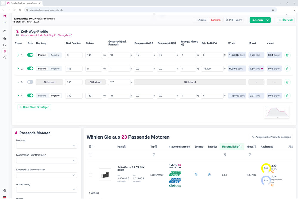
Use the MotorFinder to design your system based on load and motion profile. Match the force, speed, and required motor torque to your spindle axis.
Send us the motor drawing and the desired axis. We’ll coordinate the centering, hole pattern, shaft, and coupling, and customize the motor flange to fit your motor.
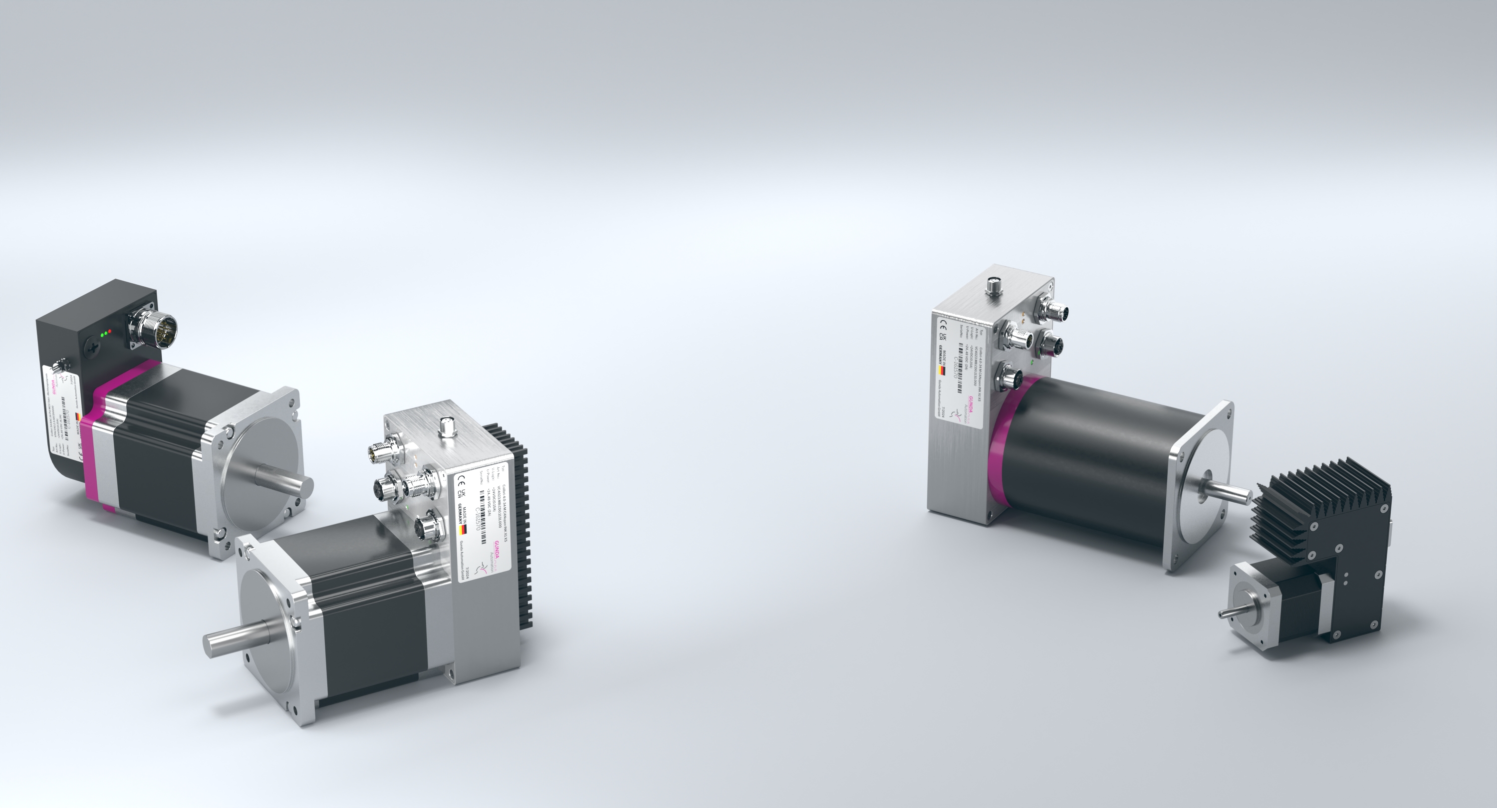
For cost-effective positioning tasks and adjustment movements. Our integrated stepper motors combine the motor, controller, and communication directly on the axis.
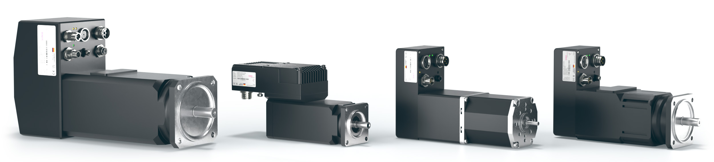
For high dynamics, rapid acceleration, and varying loads. Our servo motors combine the motor, controller, and power electronics into a single unit.
A spindle axis is a linear axis in which the rotational motion of a spindle is converted into linear motion of the carriage. The integrated guide supports lateral forces and moments. GUNDA offers spindle axes with lead screws or ball screws.
In the SK-0, a self-lubricating plastic nut runs on a stainless steel threaded spindle. It is suitable for compact adjustment tasks and lighter applications. The SK-2, MTV, MUK, and MTL use a ball screw or ball-screw drive for precise movements and higher loads.
SK-0 is the compact version with a slide guide. SK-2 combines a ball screw and a preloaded recirculating ball guide. MTV offers a slim, integrated guide. MUK has two guides with one or two carriages per guide and can accommodate high lateral forces and torques. MTL offers a wide mounting surface for heavy-duty applications.
Yes. All five series are available as mechanical spindle axes without a GUNDA motor. You can have your own motor mounted or combine the axis with a suitable GUNDA stepper or servo motor.
Yes. We offer a service to adapt the motor flange to customer-supplied motors. For this adaptation, we need the motor drawing, including centering, hole pattern, shaft dimensions, and mounting dimensions, as well as the desired spindle axis. The coupling and mounting are tailored to the specific application.
Yes. Our spindle axes can be combined with stepper motors featuring integrated control or servo motors with integrated controllers. The selection depends on the required force, speed, acceleration, duty cycle, and communication with the machine control system.
The SK-0 offers a stroke of 50 to 500 mm and a repeatability of ±0.15 mm. The SK-2 offers a stroke of 100 to 1,200 mm and ±0.02 mm. Depending on the size, the MTV and MTL achieve a stroke of up to 1,500 mm with ±0.02 mm. Depending on the size, the MUK achieves up to 1,500 mm with ±0.05 mm. The exact stroke ranges for each size are listed in the technical tables.
The lead determines the travel distance per spindle revolution. At the same rotational speed, a larger lead results in a higher linear speed. At the same time, the required motor torque and the available axial force change. Therefore, lead, stroke, speed, and load are selected together.
Yes. The MotorFinder supports the design process based on load and motion profile. The stroke, force, speed, acceleration, mounting position, duty cycle, and load application point are particularly relevant for configuring the spindle axis. We’ll assist you with the final selection of the axis and motor.
Yes. Spindle axes can be combined with other linear axes using suitable connecting elements to form multi-axis systems. We tailor the axes, motors, and mechanical interfaces to the required working space and motion profile.
The data sheets are available for download directly in the series comparison and on each product card. Please send us the desired series, stroke, load, and motion profile. If you want to use your own motor, please include the motor drawing. We’ll use this information to configure the right axis design for you.
Send us the stroke, load, speed, motion profile, and mounting orientation. We’ll tailor the series, lead, guide, and motor connection to your machine.
With a GUNDA motor or your own motor: For flange adaptation, simply supplement the existing motor drawing.
Enter stroke, load, and motion profile. Not all data at hand yet? Contact us for advice.