

 DE
 IT
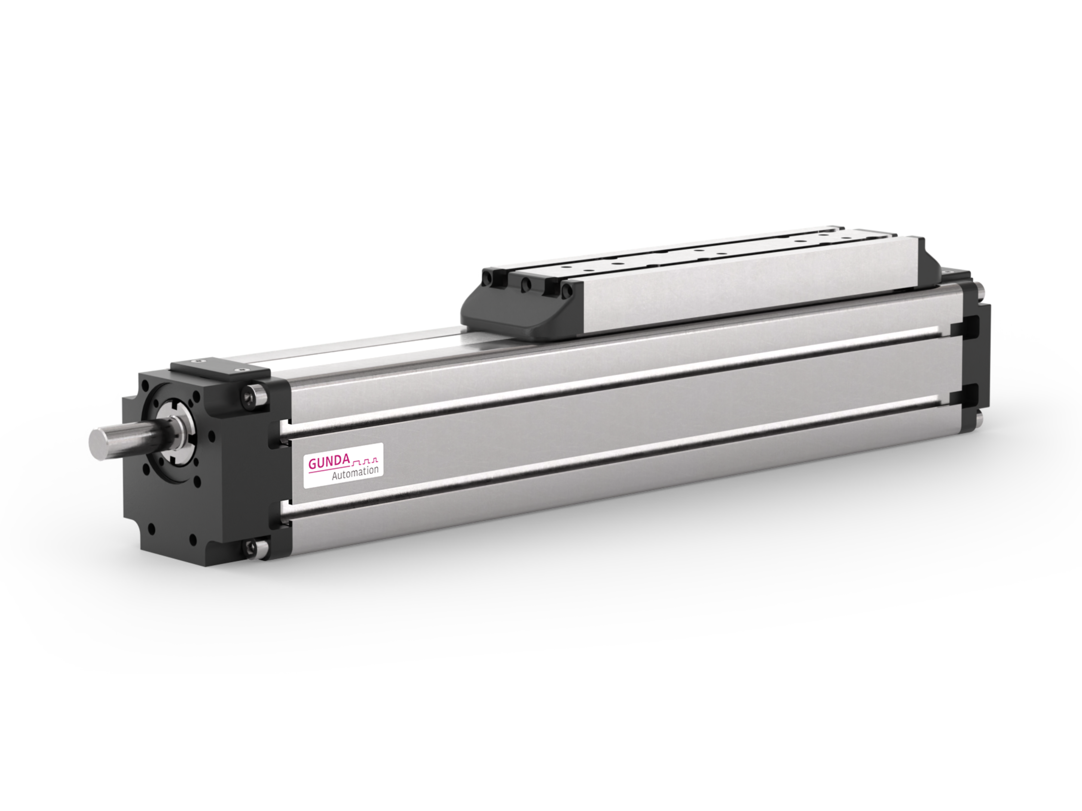
Get an initial axis recommendation in just a few steps. Your details help us develop the right solution faster.
Prepare an axis enquiry. Your entries remain in this browser tab. The draft is not yet sent to GUNDA.
FINDING THE RIGHT SOLUTION TOGETHER
Define. Assess. Size together.
01 / Application
The right questions
Stroke, mounting orientation, load centre of gravity and motion profile, rather than selection by kilograms alone.
02 / Guidance
An initial recommendation
You receive a preliminary selection. We check the details of the final sizing for you.
03 / Sizing
GUNDA checks the combination
Guide, drive and motor are assessed as a complete system. The result forms the basis for the right solution for you.
Data sources and force/moment diagrams
Core data from 21 original product data sheets and BK/SK catalogue extracts: 62 specific configurations. Stroke, lead/feed, speed, rotational speed, Fx, guide loads and repeatability are preliminarily checked wherever supported by source data. Conflicting sources and special sizing cases explicitly remain unresolved.
Technical data sources for BK: catalogue pages A5.146/A5.150; SK: A5.129/A5.132/A5.133. The positioning accuracies given there are explicitly indicative, not guaranteed absolute tolerances.
Data as of 8 November 2026. Individual limit values must not be interpreted as loads that can be applied simultaneously or as proof of service life. Absolute positioning accuracy is not equated with repeatability.

